Photogallery of our build
-
-
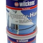
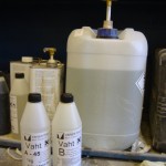
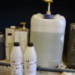
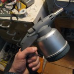
Our two component primer.
-
-
-
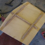
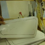
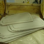
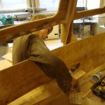
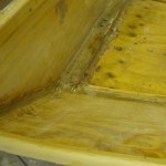
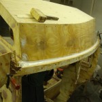
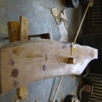
Rounded, sanded and epoxied.
-
-
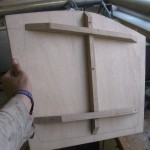
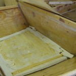
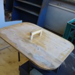
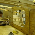
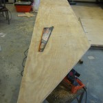
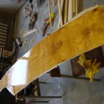
Ta-daa, inside side of the hatch.
-
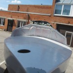
-
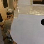
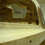
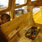
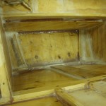
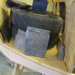
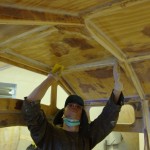
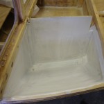
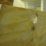
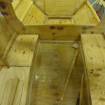
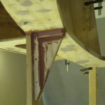
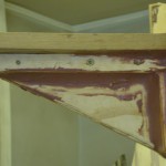
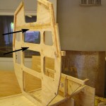
That hole leads to the forepeak chamber meant for lines and perhaps a small anchor? It is about the size of three “regular” 10 L buckets. Also needed to access forestay fastenings, seen as a gray patch.
-
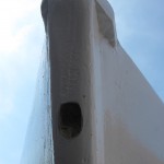
-
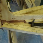
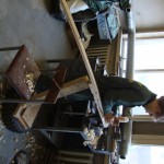
Drilling the hole was no problem, but creating this spacing hole underneath sure was. Turns out that the drill NEarlY missed the large M12 nut of the old bar. It drilled a hole trough the metal plate keeping the nut in the hole. Lucky. Anyways, it took lots of drilling and dremelling to get this large countersink. Needs to be wide for a tube-wrench to fit in there. The new bar is M10, but stornger, AISI 316 and all. thinking of simply putting a cap on this. You never know, we might break the AISI bar as well and I would not like to drill a third hole. So…
-
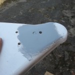
-
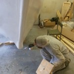
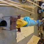
This gray patch deserves a picture of its own. Namely you can see a little gray crater next to the larger hole at the very top. That is were our 12 mm zinc-coated carbon steel treaded rod was. When we tried to remove it with a pipe wrench, it broke off, not even promising to move. Well, then there was a second try. I welded a bar to the stump (it was above deck before) and then gave it a proper blue flame heating to possibly loosen any epoxy holding the bar stuck in its hole. There is a single M 12 nut (behind a metal plate) holding the bar in the transom. In the process I burned the paint, primer, epoxy fillet and fiberglass. And with a squeaking twist broke the thread again, clean off, but a bit deeper. What a pain. So we just drilled a new hole, slightly further up.
-
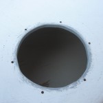
-
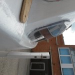
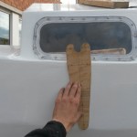
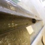
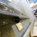
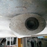
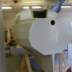
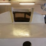
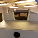
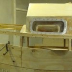
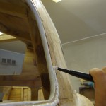
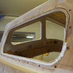
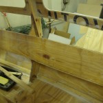
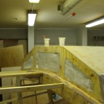
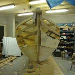
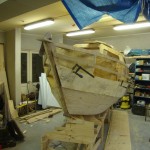
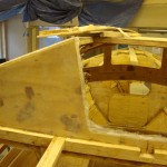
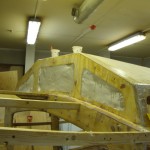
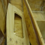
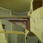
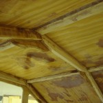
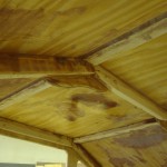
This is the forepeak hatch opening as seen before. It will have a twistable hatch on it, about 15 cm DIA. the gray is primer. Today it got a cover of paint.
-
-
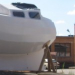
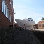
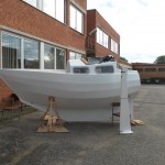
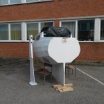
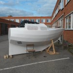
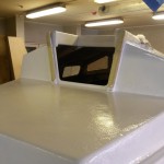
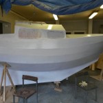
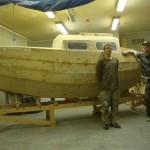
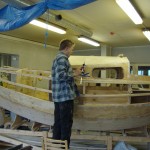
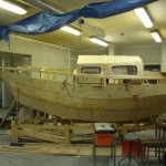
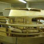
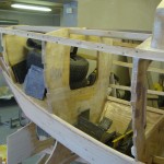
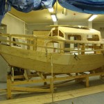
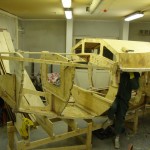
As she stands.
-
-
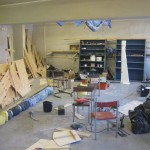
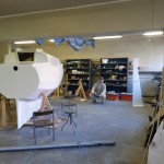
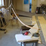
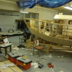
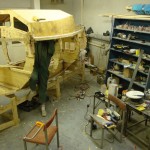
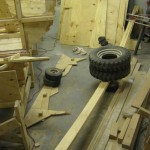
What the workplace looks like without the boat in it. Lots more room to make a mess in.
-
-
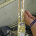
Stainless steel welding electrodes, meant especially for AISI 316 (L). Leaves a corrosion resistant weld (acid resistant too).
-
-
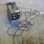
The Mot welder – it actually works, and pretty well. Average short-circuit current is 110 A. the output is not ballasted and would benefit from this, either some large capacitor or inductor. I used to weld 2 mm rods on it, but the current was too much – lots of splatter and uglyness. Plus the rods got glowing hot after about 1/3 of its length had burned. Now, 2,5 mm dia rods work excellent. They don’t start glowing, start up easier and leave nicer welds.
-
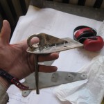
-
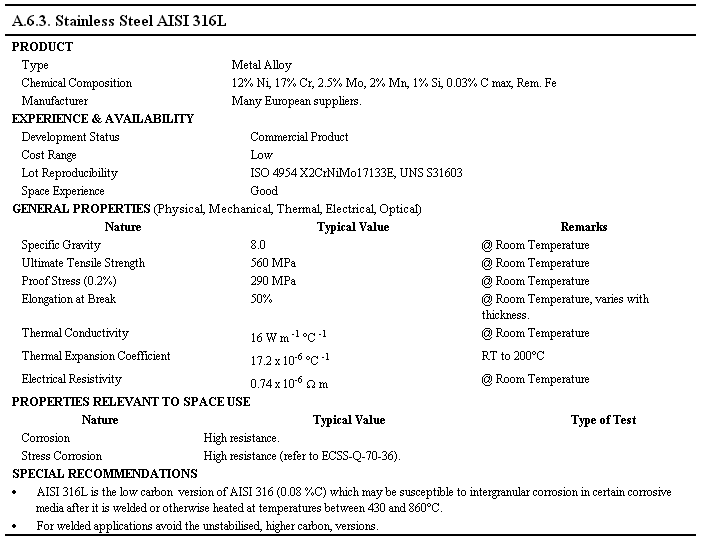
So, this piece is all AISI 316 steel. Welded up by our welder converted from two microwave ovens. Low carbon stainless steels really distort a lot when welded, compared to “lesser” steels that is. So the approach is to tack weld areas in a symmetric fashion and do filling passes in small proportions. the result is not as nice as you’d want, but it sure holds.
-
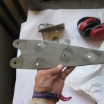
-
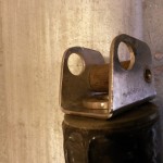
This is one of the chainplates, 4 mm AISI 316. This material eats up drills like a wonder. MUST keep the drill bit cooled, also the metal below, keep the RPM down and add lots of oil. If I could, I’d put a constant flow of oil into the drilling hole. On the two chainplates, I used up about 4 drill bits. I do not have the means to sharpen drills. It can probably also be done on a dremel, but I do not have the theoretical skill. SHould look it up…
-
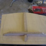
-
Work started on the vertical part of the compaionway hatch.
-
-
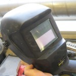
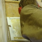
A view trough the helmet (clear mode)
-
-
I got a cheap (25 eur) autodarkening welding helmet. It is working excellent!! The shade can be regulated from 9-13 DIN. the sensitivity is also adjustable and there is a TIG welding mode. It has two sensors, a battery and a solar battery. Perhaps the only complaint is visibility. The front protection plastic has a covering film on it (like on new LCD screens), but it has bubbles in it and is, well, a bit foggy. The visibility would be better if I removed the plastic film, but I want to keep it as long as possible to protect the UV filtering plastic below. Anyways, I recommend a autodarkening helmet to any newblet welder. It makes you a ton more precise. Now i can hold the electrode with two hands.
-
-
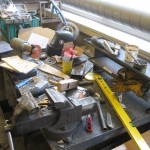
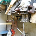
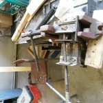
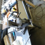
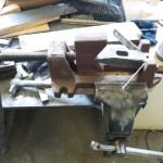
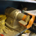
The main metalworking area.
-
-
-
-
-
-
-
-
-
-
-
-
-
-
-
-
-
-
-
-
-
-
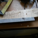
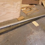
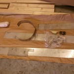
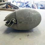
This was our steel before fitting work started.
-
-
-
-
-
-
-
-
-
-
-
-
-
-
-
-
-
-
-
-
-
-
-
-
-
-
-
-
-
-
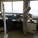
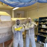
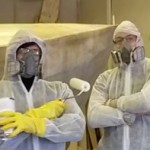
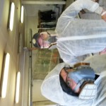
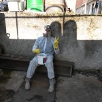
Cue Mark Snow music! The men in white will stir up all your alien DNA.
-
-
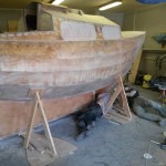
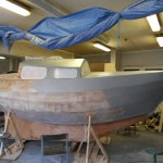
We started the day off with wearing down sandpaper and rough edges of the boat finish. We decided not to add any more filling, despite the surface texture being rough here and there. The reasonable argument is that the boat cured for a few months and we could be sure that the paint adhesion is maximum. The second, a more laid back argument is that we would not be bothered by some roughness. It is a signature. Still, we took the EPO stalagmites off.
-
-
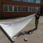
After washing the boat with water (poured buckets over it), we had some time to play around with out sails. This is the 6,5 m mast with our arched luff genoa. Still missing a boom, but working on getting one.
-
-
-
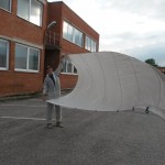
The jib took flght! Originally an Albin sail.
-
-
-
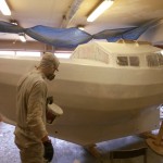
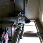
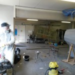
We put on our gas masks, paint suits, gloves and started painting. Did not smell bad or strong at all – that is until we got a sniff of the occasional breeze that penetrated between the mask insulation. Wow! Strong stuff. Would definitely have reached Nirvana if we painted without the masks.
-
-
-
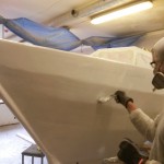
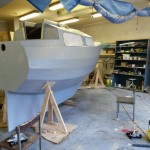
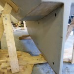
This is the first coat of epoxy primer.
-
-
-
Looking from aft to fore. The water-ballast holes in the keel are much more visible now.
-
-
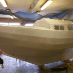
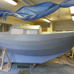
And! Whadda’ya know. It took 2,5 hours and 4*0,75 L paint to get this finish.
-
-
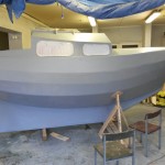
Looking good!
-

-
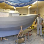
Looking aft. We definitely should have put the windows on last. But, we were ver anxious back “then” and… allright. If the day comes, we will change them.
-
-
-
Even better!
-
-
-
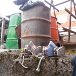
-
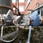
-
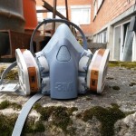
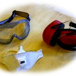
A good thing to have, the 3M mask. It has a bivalve system, good seal and well adjustable strapping. The main bonus is that the filters can be changed according to the need. Before we had fine dust filters on, this time hard chemical filters.
-
-
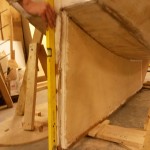
Giving it a last check with the bevel – as if we could change it.
-
-
-
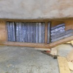
The dry fitted lead. We leveled some of the casting extrusions with the angle grinder. It was like a machinegun of fine lead pellets. the whole shop was full of little lead shot.
-
-
-
Uku getting it on with Portland cement, tight cracks and the very toxic lead.
-
-
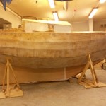
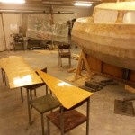
This is what the hull is now and this is what it will stay like until we paint it.
-
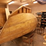
-
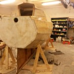
-
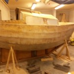
-
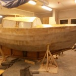
-
-
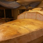
Last pieces of plywood to complete the hull. Three coats of epoxy resin.
-
-
-
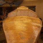
That is what she looks like!
-
-
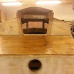
Glassing the boat is now finished. Here is the fresh glass on the aft deck.
-
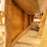
-
Getting ready for a dry fit of lead and plywood.
-
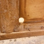
-
Part of the keel is flooded, actually about 2/3 of it, in three sections.
-
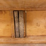
-
Lead blocks in the keel, a dry fit. Had to hammer the lead flatter since the casting form deformed as we were hammering the casts loose. First casts fitted nice, but the quality of them decreased with every pour. Hammering lead was an interesting activity. Two hammers were used, one in the left hand, the other in the right. Whilst rythmically bashing the lead, an activity good for Siberian prison camps of the past, we rediscovered one of the oldest forms of music: music of labour. It just comes naturally when you need to do physical, routine work for long hours.
-
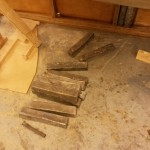
-
-
-
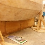
The keel side in place.
-
-
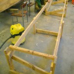
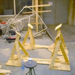
It was time to glue the keel and build new braces to keep the boat upright with the keel attached. This meant salvaging the construction rig we built as a very first thing back in 2011, when we started the build.
-
-
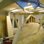
The new stands completed.
-
-
After the rear stand was completed, it was time for the forward stand to be made.
-
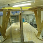
-
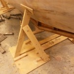
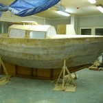
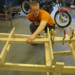
Out of the salvaged parts, an inverted design approach was taken. We decided to make two stands, one in the front and one in the back. Four tripods alltogether. The keel stands in the middle of the tripod base plate connection planks.
-
-
Starboard side, hatch on and all.
-
-
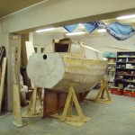
There she stands! Ready for sanding, finishing and lead bricks.
-
-
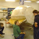
And – on the 5th of January, we flipped to boat again. This time the procedure was more organized and worked like an arm exercise of the army of North Korea.
-
-
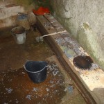
The workplace after the pour was completed. Can you guess where the melting pot stood? The wall behind the scorched area was hot to the touch. That ought to give a hint on how much power was needed to melt all the lead. A promise of good fun at cleaning up.
-
-
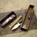
Releasing the ingots from the form had its toll on the tools. The form, on the right, lost both handles, its general shape and vigour, cracked a wall. A hammer snapped, the workshop floor suffered some damage and a second, scrap metal form was damaged.
-
-
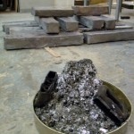
Quite an amount of impurities were skimmed of the molten lead.
-
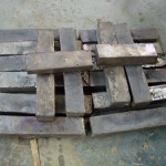
-
All done! All this work was needed to put the metal we had into another shape. Fantastic how things work.
-
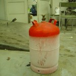
-
We rented the gas and the burner from a local tool-renting company. 11 kg of industrial gas and the burner. On the picture is the gas container after we finished pouring the lead. We do not have snow on the ground in Estonia, but that evening it was on the gas container. Thermodynamics in action – the gas expands and chills the container. We calculated that we needed roughly 3 kg of butane to melt all the lead we had. We definitely used more. This was due to losses. Smelting lead outside with near freezing temperatures has its drawbacks. Not enough though to keep the 50-60 kW burner at bay.
-
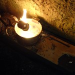
-
It took more than an hour to finish the new pot-handling-frame. This time, it worked. Welded from scrap metal, it held like a charm. On the picture, the torch is on idle, meaning not as hot as it can be. At its hottest, the flame is not as bright, meaning that the energy is transferred in a different area of the electromagnetic spectrum.
-
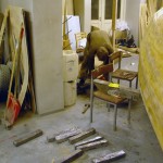
-
The casting form was not perfect. It did not want to let go of the ingot. Here Joosep is improving his general fitness when trying to release the form. The form walls were inclined to aid release, but the welds were awful (chicken shit they call it on the web) and probably held the lead in. In the end we did find an optimal way of loosening the pour.
-
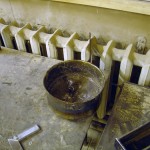
-
Unfortunately we had not thought trough the process of handling our pot filled with molten lead. Soon, due to temperature, the handles broke off and we actually almost spilled a potfull as it fell to the ground. Luckily, we still have our limbs and vision. After a first jury rig, the spot welds broke off the sides of the pot as well. So, a more elaborate design was needed. Here again the momemade microwave-oven-welder came handy.
-
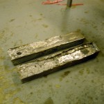
-
Our first casts were sloppy. We cooled the form by pouring water onto the hot lead. At times, if poured too early, this caused a jet of lead to burst out of the solidifying brick. Perhaps because water got between the bottom of the form and the lead, evaporated, expanded and pushed its way trough until emerging at the top? We also discovered that skimming off smelting residues had its benefits do achieving a proper pour. On the lower bar, which was our very first, we did not skim any residues off the surface of the liquid metal. An experiment.
-
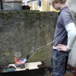
-
On the 30th of December we took the next step in smelting lead. A max 50-60 kW industrial gas burner. A potfull of lead melted in about 5 minutes. A vast improvement over our last experiment. This was great fun.
-
-
Then we covered the boat in a smoothing microballoon-epoxy fillet.
-
-
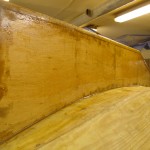
The covered side of the keel, with a few layers of epoxy. The other side will be covered once the boat is flipped and lead bricks added and braced with cement plaster.
-
-
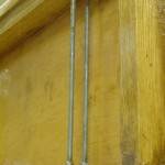
We added in total four threaded bars to help keep the keel attached to the keelson. This construction is not in the original plans, but was improvised by the builders to aid soothe the fears of loosing a keel at sea.
-
-
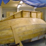
The keel was then glued in place with confidence.
-
-
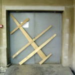
We were slightly frustrated by the “fact” that we could not put the keel on in the workshop where we are. Several plans were devised on how to move the semi-completed boat to a new area, fix the keel on it and then transport the boat closer to the sea to wait the sailing season. We discussed renting a trailer, buying a trailer, renting a lorry and whatnot. Then, Joosep had the bright idea to actually measure whether the boat could fit trough the door. We then constructed a maximum area cross section of the boat, with the keel attached. And voila – this is the result. It fits trough! We had been building the boat 2,5 years knowing that we could not move the boat out. A simple 30 minute experiment proved otherwise. What a great release.
-
-
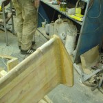
The rudder shoe has been installed, this joint was the first area where we tested our new biaxial cloth. Wow, is it better or what. It soaks up epoxy much easier and also, since it is biaxial, bends around curves with ease (as long as applied correctly).
-
-
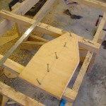
Joosep continued with the rudder shoe. You can step on it when on the way back onboard the boat.
-
-
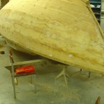
After abandoning foundry processes we continued with other work needed to be done. Again, our ever so faithful PVC sewage pipe want water kettle boiling system came handy. Here you can see the gunwale stringers steamed and temporarly fastened to the boat. Solid oak with a few scarf joints.
-
-
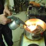
We argued that there needs to be a liquid lead layer covering the bottom of the pot to improve conduction. Uku took out his 1,5 kW butane burner and went to the rescue. Indeed, it helped melt the lead, accelerated the process, and a pool was formed. But the process was asymptotic – after removing the torch and adding lead. The pool froze, only a small part of it remained liquid in the center of the pot, where the heat flux was greatest (edges of the pot were cooled by air). All this, meaning, all this nothingness had taken us an hour. Bad news – we needed more power.
-
-
Our lead needed to be melted. Initally we tought of making a big fire under a kettle. There is still no snow in Estonia, still no minus degrees, still no water freezing, still not so cold in the apartments, so we would have had plenty of firewood to use. Doug Jackson of svseeker.com smelted his lead with a wood furnace, all 4 tons of it, or more. But that would have meant moving the lead from the garage to the source of timbre and then back again. Plus, it was not very certain how we would put the kettle into the fire, how to keep heat losses minimal and how to pour the lead. We sought a simpler solution. YouTube came to aid us in our confusion and an idea was formed in the mist: use a powerful electric stove. So one good day Uku brought the steel pot and Joosep brought the stove. Two material sacrifices from our everyday lives. One of the heating elements of the stove was fried (dead, no conduction), the other, a 1,5 kW one, worked. We calculated that it would take at least 15 hours to melt the lead. A doomsday figure, but we had to try. Luckily, our shop has good ventilation, so we turned the stove on, put the pot on it, some lead into the pot, a heavy steel lid on the pot and started waiting. Soon, maybe 30 minutes later, the lid was steaming. All the epoxy and whatnot-gunk was burning off the lead. And behold – a little bit of it was even melting (melting point of lead is around 350 deg C).
-
-
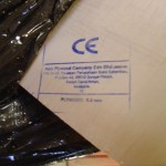
Asia Plywood Company Edn End, Malaysia. There is a ton of illegal hardwood going out of Malaysia. Lets hope that ours is legal and the indochinese tiger will have a place to live in the future as well. “At current rates of forest lost the rainforests will disappear within a generation.” – Wikipedia on Malaysian wildlife. Any solutions?
-
-
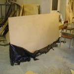
Mother of pearl of the world of plywood – certified marine plywood, 9 mm, 5 ply tropical Meranti. Rot-boil-weather-water-UV and whatnot proof. We bought two sheets for covering the keel. We argued that since the keel is not going to be fiberglassed, then we want the wood to be as rot resistant as possible.
-
-
We had planned our work frenzy since the beginning of autumn. We aimed towards the Universitys Christmas/new-year holiday. Our initial plan was to finish the boat completely. It was a good estimate and we did not miss mark too much. Work started 10 o’clock (am) on the 24th of December. Forehad we obtained a new roll of fiberglass: 50 kg of 220 gr/cm2 biaxial fiberglass, supplier: Bang&Bonsomer.
-
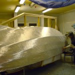
-
Then we decided to glass the boat. Before of course we fiberglass-taped the planking seams with a 10 cm wide fiberglass tape ordered from China via Ebay. It had a most pleasing postcard in the package.
-
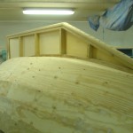
-
View from the port side – now the dry fit is complete. All is in place, the shoes, posts, forward stem capping and plywood.
-
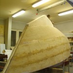
-
From a different angle – the keel mockup without keel shoes/leading edges.
-
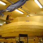
-
Almost done with one side. Working on the keel cappings.
-
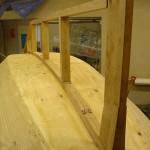
-
Progress with the keel dry-fitting. Tapering the keel timbre took a healthy amount of time. Done with the handsaw, router, handplane and the chisel.
-
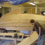
-
After being convinced of the quality of the keel superstructure mockup we decided to go ahead and cut out the keel side plates. At first, tracing the curve seemed tedious. Joosep took vertical measurements of the keel profile every 10 cm or so. Then cut out the shape. It was satisfactory, with a precision of 1 cm or so. Then we recalled how Doug Jackson of svseeker.com drew the curves on his steel plates – put a pencil flat on the curved surface, place the joining plate onto the curve and trace with the pen – 95 % match of curves.
-
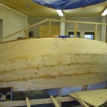
-
We started by constructing a dry fit of the keel. This meant that the keel tailpost had to be made (the heel of Achilleus on our boat), keel posts fixed, keel edges fixed and the ever-so troublesome forward transom capped.
-
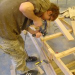
-
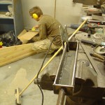
We could not glue the keel on, since we “knew” that it would not fit out our garage door. Thus we continued with other works that had to be done to get the boat finished. Here Joosep is drilling a hole trough the rudder to add a threaded bar in order to give additional strength to the laminate. This should have been done forehand – drill a larger than needed hole trough each laminate piece, before laminating. Now, due to low accuracy, four holes were needed to get a good hole trough the rudder. Sidebores were filled with epoxy. Learn as you go – right.
-
-
While Joosep worked on the rudder, Uku continued welding the lead casting form. The DIY MOT welder was resurrected and put to good use. Turns out that stick welding takes time and patience to learn. A few tips: constant arc length and keeping an eye on the metal puddle.
-
-
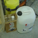
Along with the new roll of fiberglass arrived our third 30 kg batch of West System epoxy resin. This means we have bought 90 kg in total. Should have bought a larger canister to begin with. Learn as you go, they say. We depleted our second one and now the new one is half way through.
-
-
-
-
-
-

-
-
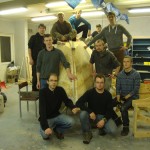
-
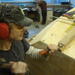
-
One of those moments when you get to take a blade to your boat. Uku chiselling away at the keelson. We needed a slot to fit the tailpost capping in. Turned out well.
-
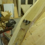
-
One of the problematic spots on the boat. This the heart of our forward transom. The bolts hold the forwardmost bulkhead to the keelson. The problem is that they intervene with the shoe of the keel. We will not give it 10 out of 10 on the aesthetics chart, but a 8 out of 10 definitely. You will see the result later. It requires some additional capping.
-
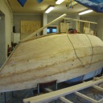
-
What to boat looks like when flipped. We have done lots of sanding as well. Most of the corners have been rounded. That took at least 3 sanding belts of our sander and a whopping two sharpenings of the hand plane. Lots of screws had to be removed, but only temporarly. We will put them back later. That is the life of a boatbuilder. Put screws in, take them out later. Put epoxy fillets on the boat and then sand them later.
-
-
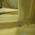
A close up of the mortice joint. On this picture there are three joints. Also, you can see that some chiselling has been done on the keelson. We need to taper it. Of course, this was to be done way before, but we have a thing for building in the wrong order.
-
-
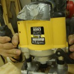
Routing a tailpost mortice.
-
-
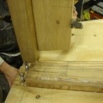
Before creating a mortice joint for the tailpost.
-
-
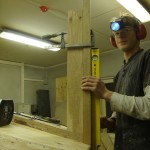
Voila! There are four joints hidden in this piece of art. Well strong. Dry fitted without any screws and it stands solid. Just forcing it level by hand. One might wonder what is the boatbuilder doing with a headlamp as one can clearly see a perfectly well lit backdrop. The headlamp was used to illuminate the routing area, as it was shadowed by the big head of the boatbuilder.
-
-
-
-
-
It was a rare moment when we actually had very little left to do. So we simply spent 2 hours cleaning the shop. Now we have organized a team of friends to come help roll the boat over so we can start building and dry fitting the keel.
-
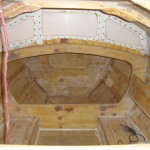
-
A flashy shot of the inside. All is glassed, except for a few uncritical spots not seen on the picture. Once painted, it will not look that beat up from fillet stains.
-
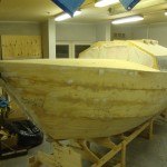
-
A view from front. The decking process required excessive force at the very tip of the boat. 9 mm ply was hard to bend to such a radius. We had to use the ceiling as a support for a massive block of wood which we used as a lever. But it holds well, for now at least. Screws and epoxy work wonders.
-
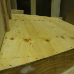
-
The plate of plywood, the aft deck, name it as you want, feels good and solid to sit on it. To the left you can see the companionway slides. The companionway is also finished. Some work left on the hatch itself.
-
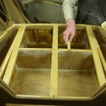
-
We have no footage of covering up the fore. Here is Uku applying epoxy to the aft framing. A plate of plywood is in order. Pre glassed from underneath.
-
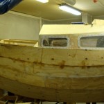
-
-
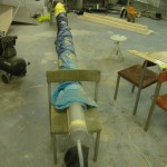
We had to blow some dust off of our old good PVC steamer setup. This time it was needed to steam an out of proportion small piece of oak for the hatch. Worked like a charm.
-
-
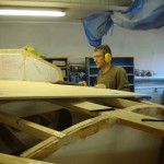
First deck plate fit. Looking good.
-
-
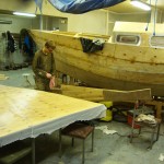
-
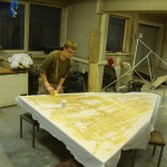
Glassing the deck plate and rudder sheet.
-
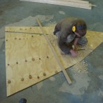
-
Joosep working on scarfing the bow deck plate.
-
-
-
What the hatch slide looked before it was decorated with bevels.
-
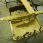
-
Pieces waiting to be glued to the deck. Pieces of the companionway hatch and slide.
-
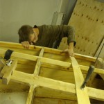
-
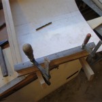
Out of blue, while beveling the gunwales, we got the idea of clamping a strip of plywood to the kingplank as an arch reference. Worked well!
-
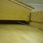
-
The process of fitting a companionway hatch stainless-acid resistant steel runner. It took some angle grinder discs to cut two stripes. Nothing compared to what Dough Jackson has been cutting for his 25 m sailboat. But we have our moments, in metalworking too.
-
-
This is what the runner/slide mate looks like. All dry fitted.
-
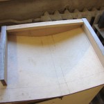
-
Runners dry fitted to the hatch.
-
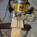
-
Routing the companionway hatch runner slots.
-
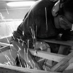
-
Alexei Stahhanov again producing more than the work quota requires. “This month, we ground down ten additional screw points. Today, the Žiguli (USSR beer) is on me.”
-
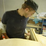
-
Uku working on the hatch slides. It took some mental and physical effort to get the things alligned properly. The boat is not that easily accessible, so every time you forget to take a pencil with you, you have to climb out of the companionway and down the aft of the boat. Takes time. But practice makes perfect. Feeling more and more related to the great apes.
-
-
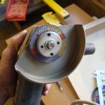
My personal agnel grinder record. I wonder if there is a minimum diameter limit on cutting discs.
-
-
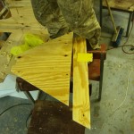
Joosep started on the bow chamber, in which we plan to store some rope and the bow anchor. On the picture, the pieces which separate the usable area from the foam filled buoyancy section.
-
-
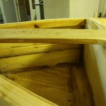
The bow chamber without paint.
-
-
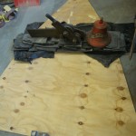
The result of finding out that the optimum pressure for a wood-to-wood epoxy joint is actually rather high. In total over 300 kg of weight, but not that impressive when concidering it in newtons per square meter.
-
-
The bow chamber painted. We decided on using, as recommended by John Welsford, an oil based enamel paint. White, of course.
-
-
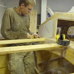
Joosep tightening stainless steel acid resistant bolts. These keep the polycarbonate in place. A tight fit. The deck plate needs to shift forwards a few centimeters. That in itself is not a problem, but the bulkhead and arch should have a fillet. It is not there yet. We’ll figure it out.
-
-
The finest photo we have of our boatbuild so far. Jackson Pollock would have been proud.
-
-
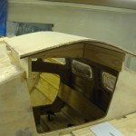
This is what the companionway roughly looks like. Some details have been omitted from the picture. Mostly oak, except for the arched laminate, which is 2×4 mm plywood. Excessively strong.
-
-
The ridicculous lamination process of the companionway slide hatch. There was about 300 kg of lead involved, and lots of aditional tightening with clamps. It was actively bent until first sounds of cracking were heard. Then, pressure was slightly reduced.
-
-
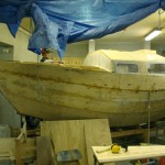
A view of the boat as is.
-
-
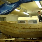
Slightly grainy, but still good. An exercise in vertical lines, fine arts, fine architecture: the deckline tilts right, cabin line tilts left and the companionway hatch tilts right.
-
-
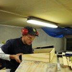
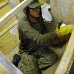
Uku working on the companionway hatch.
-
-
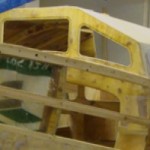
Joosep laying epoxy fillets to the new planks.
-
-
-
-
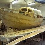
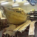
Port side of the boat with three glassed planks waiting to dry. Great fun it was this time. We are getting better at this. Henry Ford would have been proud.
-
-

-
-
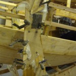
The rudder sheet was laminated with large oak cheeks. Good strong wood. Now we simply have to give the sheet some shape with a plane. Then glass it.
-
-
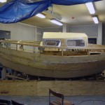
There she is. New plank on and all, looking good.
-
-
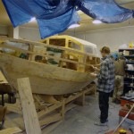
A rare, or actually the first, shot of us two working on the boat non-posed. Picture taken by Artur.
-
-
“A very simple 7’4″ x 3’10” dinghy, made out of simple materials, using a simple construction method and just the basic tools,” as the designer’s homepage says. The displacement before swamping is around 360 kg.
-
-
Anni asked me for advide on how to build a boat. That was in the summer. Now she has her own. A rowing dinghy out of marine plywood. Simple and elegant design, inspired by Portugese fishing boats.
-
-
A view of the aft shelving and liferaft well. Artur’s boat is to the right. The little brother.
-
-
A fine looking boat that Artur has made. He went with simplicity and with the aim of getting the boat done as fast as possible, to get sailing. That is why there is no paint for the moment, but that will be added. As said: okume. The first time I ever saw marine plywood. Looks nice, no spots, nothing, just wood.
-
-
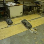
The last lamination we have to do for plaking. These are the to-be starboard planks. They call it a scarf joint.
-
-
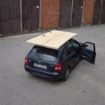
How our new plywood arrived, a lot less fuzz than two years ago. We had a truck delivery back then.
-
-
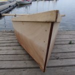
Artur’s boat on the shore of lake Saadjärv. No paint, just okume. Seems to work fine, its hard stuff.
-
-
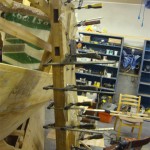
This is how we laminated the cheeks of the rudder sheet, two tiller holes are visible, one for inside steering and the other or on-deck operations.
-
-
-
-
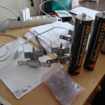
Joosep went web sopping and returned with: stainless steel countersink bolts, wasers and nuts. Then there are three heavy duty rudder hinges and two canisters of Sikaflex, which is supposedly godlike for adhering cabin windows. Smells good, like eating an apple, and has no “kills on touch” warning labels. Contains no cyanide, good to know!
-
-
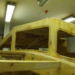
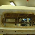
We grooved our window frames, this, it turns out, has benefits. A) keeps the bead in place b) acts as a reservoir for adhesive, yielding an even dispersion when contact surfaces are pressurized.
-
-
-
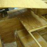
A shot of the aft shelving progress.
-
-
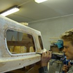
Uku laying a Sika bead.
-
-
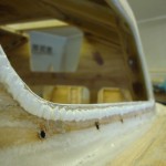
Looks like whip-cream. It is not.
-
-
-
-
-
A generaalshot. The plank is test fitted, but the stringer behind is not, that is glued.
-
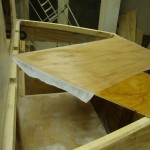
-
-
-
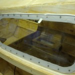
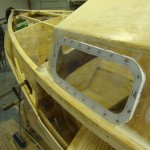
A fitted cabin window. The white smudge in the upper left of the window is from contact with acetone, which we intended to use as a residue cleaner. Not a good idea, keep away!
-
-
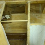
-
More aft shelving. The tape rolls are going to be replaced with a gas stove in the future. In the left of the image is a watertight buoyancy compartment. To be covered.
-
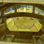
-
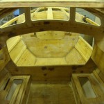
-
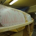
-
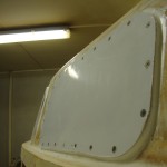
-
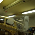
-
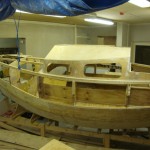
-
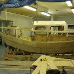
-
A profile shot.
-
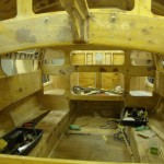
-
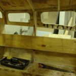
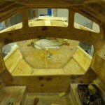
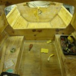
A view of the inside as it pretty much is at the moment.
-
-
-
-
-
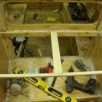
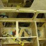
A shot towards the galley. Instead of the tools we will have a gas stove, below it, we are concidering a metal plate.
-
-
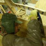
Joosep trimming shelve base plate edges with a saw.
-
-
-
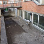
A promise of the future: this is the way we will have to take our boat out.
-
-
-
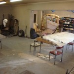
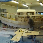
And… this is where we stand at the moment with our project. The wings are not for the boat. They are being built for a RedBull-flugtag event by the Technic club folk.
-
-
-
Bench hatches are complete. They stand fastened until we get to making gaskets.
-
-
-
-
-
-
The all-great polycarbonate glass. 8 mm thick, rated bulletproof.
-
-
-
-
-
-
Behind the galley is the well for the liferaft. This is it, the hole.
-
-
A test setup for the inside steering tiller. To the left is a solid piece of oak which is to be laminated to the rudder blade standing in the right of the picture.
-
-
The rudder blade, has an oak leading edge.
-
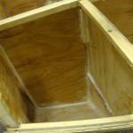
-
A watertight foam chamber in the aft.
-
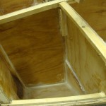
-
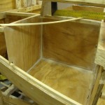
-
To-be shelf.
-
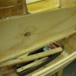
-
-
-
-
-
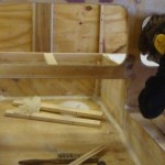
-
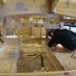
-
A fine picture, Joosep grinding down some metal on the fresh benchtops.
-
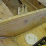
-
One of the inspection ports. The lid screws off counterclockwise. This is straight under the mast. In the plans, the water goes here.
-
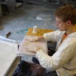
-
Uku glassing shelves.
-
-
-
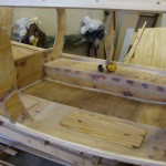
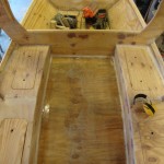
A good view of what the interior looks like when entering from above.
-
-
-
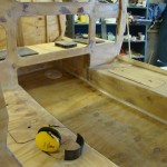
-
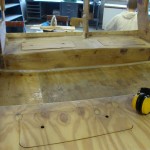
The footwell is now covered, in there is an inspection hatch to the double floor. Buoyancy compartments are on the left and right side of the well.
-
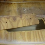
-
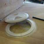
-
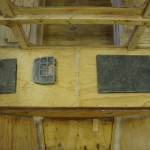
A close up of the “Made in China” inspection port. This is in the aft watertight compartment. Nothing to inspect yet: blue foam, hard epoxy and expanded foam.
-
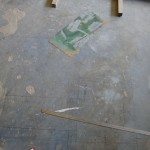
-
Joosep used the floor as a “canvas”. Laying out the windows and investigating what geometry should our sheet of polycarbonate have. Turns out that that stuff is expensive. Initial waste percentage planned: roughly 20 %.
-
-
-
-
-
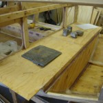
-
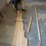
-
Initial setup of the rudder. Next: need more hardwood for laminating the tiller area, need some threaded bar to tighten all the planks when laminating, need a sharper plane. Plus there is the question of rudder hinges. We have still not found any feasible solution in webstores. Feels like it is going to be DIY. Oh yea!
-
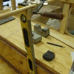
-
Cutting section walls for the shelves is an exercise of analytical geometry with hardware applications. Took 2 hours to measure out one sheet. It did not come out perfect, but good enough. Later on that.
-
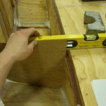
-
-
-
-
-
-
-
-
-
-
-
-
-
-
-
-
-
-
-
-
-
-
-
-
-
-
-
-
-
-
-
-
-
-
-
-
-
-
-
-
-
-
-
-
-
-
-
-
-
-
-
-
-
-
-
-
-
-
-
-
-
-
-
-
-
-
-
-
-
-
-
-
-
-
-
-
-
-
-
-
-
-
-
-
-
-
-
-
-
-
-
-
-
-
-
-
-
-
-
-
-
-
-
-
-
-
-
-
-
-
-
-
-
-
-
-
-
-
-
-
-
-
-
-
-
-
-
-
-
-
-
-
-
-
-
-
-
-
-
-
-
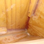
-
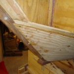
-
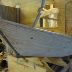
The forwardmost part of the plank.
-
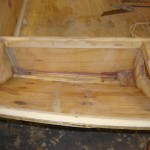
-
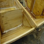
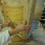
Cabin and plank intersection, this is where the seats will be and compartments under then.
-
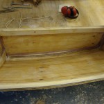
-
More of seat compartments.
-
-
-
-
-
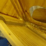
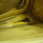
Working on the starboard side stringer.
-
-
-
-
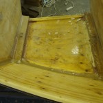
Some fine wood-dust filleting.
-
-
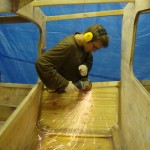
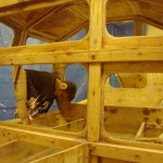
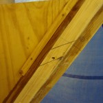
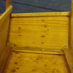
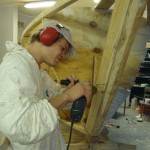
Joosep grinding down screwpoints which went trough the stringer.
-
-
-
-
-
-
-
-
-
-
-
-
-
-
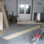
Laying out the building rig logs.
-
-
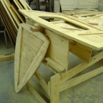
One of the forwardmost bulkheads we made. This was abandoned with three others of its kind.
-
-
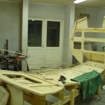
A more complete entrance bulkhead with some support structures.
-
-
-
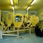
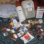
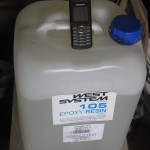
Our first anticipations on the tools we were going to need were, well, low..
-
-
-
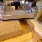
Routing the floor bevels was fun. Lots of dust though.
-
-
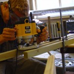
Uku working with the generally loud router. Like an air raid alarm.
-
-
-
We dared to take the boat out of the jig for the first time, still able to lift it.
-
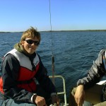
-
The builders: Joosep and Uku. Sailing on lake Saadjärv.
-
-
Even with the forward bulkhead design finalized, we still had to find a solution to laminating and bolting the forward transom.
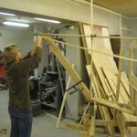
-
-
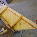
This is where our troubles with designing the sharp bow started. We tried lots of different methods, one stranger than the other. Finally we settled for a mundane approach: just bend the stringers on and see where they land.
-
-
-
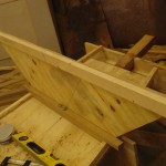
The smallest bulkhead. This lies at the aft and serves as a locker wall.
-
-
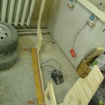
The central bulkhead in making.
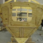
-
-
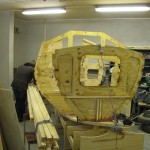
-
Fresh stringers at the garage, it was a fun ride.
-
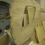
-
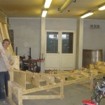
-
The famous jazz saxophonist John Coltraine has a song called “Great expetations,” this is the very moment for us. We could already see the boat in our minds.
-
-
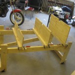
This is what it looked like when we started, the rig.
-
-
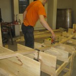
Testing the bending properties of oak.
-
-
-
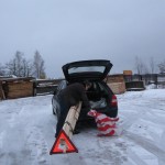
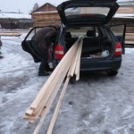
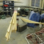
Loading the longwood onto Jooseps’ car.
-
-
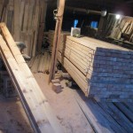
More fresh stringers, 2012. winter.
-
-
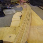
We cracked many stringers and needed new ones. The mill owner was very kind.
-
-
-
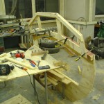
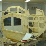
The windows fasten to the laminate arch.
-
-
-
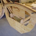
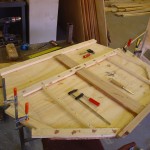
The center bulkhead with a fascinating plywood laminate arch.
-
-
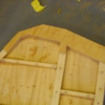
The first bulkhead we completed was the aft transom.
-
-
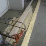
-
Our oak pile, some pine as well.
-
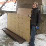
-
Joosep with our fresly arrived plywood, 2011. spring.
-
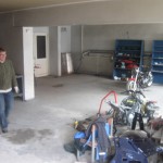
-
Our build garage before the materials arrived.
-
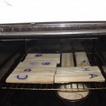
-
Baking the plywood.
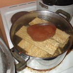
-
-
Testing out our cheap plywood with a boil test.
-
-
-
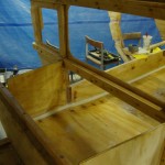
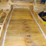
Joosep completed the double floor build, 2012. winter.
-
-
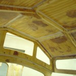
-
Filleting and glass-taping the inside took weeks and weeks. Sanding was also included in the programme.
-
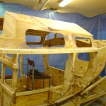
-
Here you can see the cut windows, half glassed roof and the new blue backdrop.
-
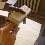
-
Take a hacksaw blade and break a little bit off. Fix this between two pieces of wood and apply pressure with a clamp until the blade bit is fixed tight. Go to phase 2.
-
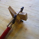
-
Use the composite tool to scratch a slit into the hatch outline. Remember to pull the way which the teeth cut. Usually hacksaw blades are unidirectional.
-
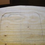
-
Only cut with the composite tool until you have a slit wide enough to fit your jigsaw blade trough it. Then cut the hatch out. This is what the end product should look like. Nice and tightly cut.
-
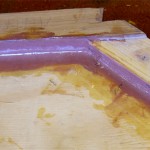
-
Here you see a fillet applied as described above. First the purple fillet mixture was added to the corner, then roughly rounded with the round scraper and then the tape was added, tapped into place after which a clearcoat was applied.
-
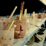
-
Here you see a shelf full of dried and released jam-cup sessions. The sticks are in there solid. This form easily pulls out of the jam cup, making cleaning easy.
-
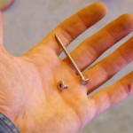
-
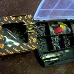
What happened when we tried to put a stainless-acid resistant screw into wood.
-
-
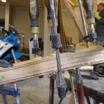
On the left are the nanocoated strong screws, to the right a variety of crappy stainless steel screws.
-
-
-
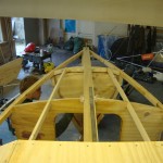
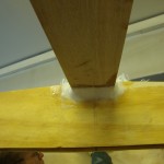
We decided to add more stringers below the deck, as we were afraid of stepping trough the decking.
-
-
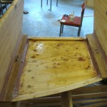
-
-
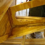
The fore knee. 2012 spring.
-
-
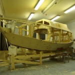
A shot from 2012. early summer.
-
-
-
-
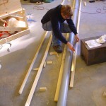
After cracking even some of the new stringers we decided to build a boiler: 5 m of PVC sewage pipe and two water boiling kettles. Worked like a charm.
-
-
-
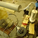
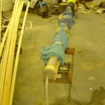
One of the boilers failed and we had to rethink the setup. Blankets did a good job isolating the PVC tubing. One kettle proved fine.
-
-
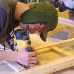
Here is Joosep routing with earplugs and a stylish hat. We decided that our routher-ploughing is not the finest method for creating scarf joints and went for hand planing the surfaces later, which works out fine with a sharp blade.
-

-
Here you can see the other side of the flipped boat, the deck. Stringers will be added underneath the bow decking for support.
-
-
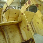
A shot from the inside. Besides the plank there is a hint of shelves on the middle bulkhead – a bracing stick. The shelve plywood has been cut.
-
-
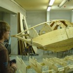
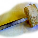
Marvelling at the creation. The empty building jig is in the foreground. Took a few hammer blows to free the keel from the profiles. In the process we unfortunately borke our wooden hammer. Will be repaired.
-
-
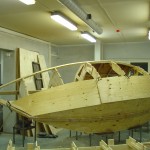
This was a very nice sight to see. The bulkheads actually look like a boat now. A temporary setup for now. It is a massive plank though.
-
-
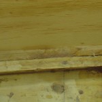
This is a shot of the bottom panel and the side plank joined by the laminated chinelog, beveled with a hand plane today. The fit is very snug, all good. Fiberglass will be on both sides of this plank.
-
-
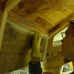
Uku glass-taping and filleting the cabin after the portside window-panel was installed.
-
-
-
The green man doing filleting on the interior.
-
-
Filleting..
-
-
The gunwale stringer can be seen, as the overall progress so far.
-
-
Drawing those fillets takes some time to hone, but it all works out for the best. Anyways, epoxy is good, since when you cut wrong, epoxy comes to aid and replaces the missing part.
-
-
On the inside, we covered the plywood with flag fabric, works like a charm.
-
-
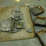
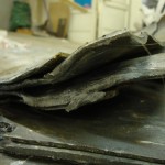
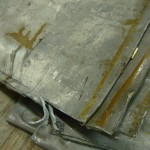
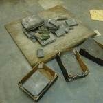
This is it, roughly 300 kg of lead. Does not look much, but it certainly feels much when lifting it. We dragged this lot into the garage with 3 or 4 sessions. Very soft, very heavy, fery unearthly.
-
-
-
-
Our ballast – 300 kg of lead. Previously used for roofing.
-
-
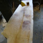
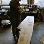
Glassing the sidepanels before applying them to the superstructure. This task proved a bit difficult, as we have a very thick fabric, which did not want to soak in the glue. Prewetting the surface below helped a lot.
-
-
-
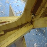
A little detail of the second layer of chinelogs installed some days ago. Now epoxied in place.
-
-
-
-
-
-
First larger glassing project, took us hours.
-
-
-
-
-
-
-
-
-
-
-
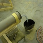
The oozing end of the boiler system.
-
-
-
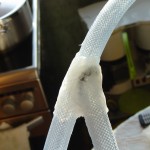
-
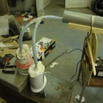
Some silicone RTV to seal up the stitch.
-

-

-
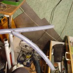
-
This is by simple definitions a 1 cm inner dia. braided plastic see-trough gardening hose. The Y joint was done by stitching the ends together and RTV – siliconing the joint. Results are very good, except for the tubing becoming very soft in steam, eg. a stiffer spaghetti.
-
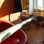
-
Here is a picutre of the very first full lenght steam test of the tubes. It took the span of two rooms to set up the rig. It worked just fine. With two kettles powering the input, there was a roughly 5 min. delay before steam started coming out the back end. Heat was lost along the lenght of the pipe and steam condensed into water. The piping felt hot to the touch all along the tubing.
-
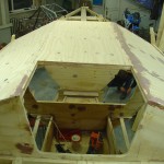
-
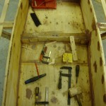
A sweet view of the top and bow of the boat. This is how the boat is at the moment. Got three gunwale stringers on. Portside is screwed in place.
-
-
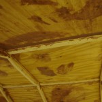
Both of the bench sides are done.
-
-
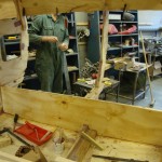
Another view of the interior. Some minor reinforcement and glassing to be done here. Paint ontop of it all.
-
-
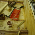
Left bench sidepanel. They are very solid now, as is the whole boat. A thump of the fist sets it off spunding like a dampened cathedral bell (hell yes, fancy)
-
-
Sidepanels were coated with epoxy from both sides. The second layer will be added later.
-
-
Hey look, it’s the plumber.
-
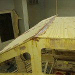
-
Starboard side panel in place, needs sanding.
-
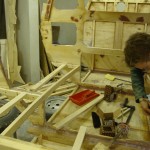
-
Bench stringers are solid. Basically under them will be compartments for whatever. Hatches will be straightforward.
-
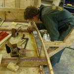
-
The green man working on getting his hands covered with epoxy.
-
-
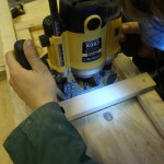
Unfortunately, the router bit a screw that night. Fortunately, the bit survived.
-
-
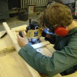
The green man again. The dentist from hell, working on a bevel. This time the wood-to-wood friction surfaces were covered in thick grease. Worked like a charm. Candle wax is not that good to use, since it can shed little bits onto the work. I’m not sure on how epoxy sticks to candle wax. Probably not that well.
-
-
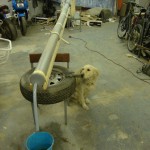
This is an early Marcel Duchamp exposition, as title says :”Steamer with dog.” If anyone is interested, the starting bid is very high.
-
-
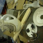
How to fix a kettle. Instructions: take lots of things out, put a few back. Plug and play. Basically, seems that the kettles are not that used to steaming for hours in a row. Lime sets on contact surfaces, such as the switch.
-
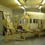
-
Getting there. Today we completed 3/4 of the gunwale stringer project. More pictures on that.
-
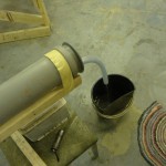
-
Very straightforward here, a hose and a bucket. Should ring a bell for the male reader.
-
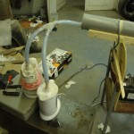
-
A duo of kettles powering the steamer
-
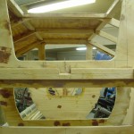
-
Looking forwad, literally and metaphysically. Looking forward to sitting on that hatchway, trimming the sail and setting course in a good breeze..
-
-
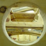
This is where the tiller, or rudder stock will go into.
-

-
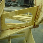
Another beautful knee. We are thinking of a anchor storage here, and foam floatation.
-
-
Beautiful knees of the boat.
-
-
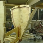
The final forwardmost bulkhead.
-

-
Looking aft inside the cabin. Window-sidepanel is installed temporarly, fitting purposes.
-
-
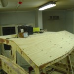
The cabin roof is very pleasing to watch.
-

-
This holds the transom to the keel.
-
-
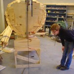
Here is a little recollection from the past. We pondered on how to get the kingplank true to the keel. So we used nuts, bolts and string to draw a straight line relative to the keel onto the ground. Then Joosep used his shoelace to aim the big guns at the meridian. In the end, the method proved unusable. But we learned that in the process, which is all the fun.
-
-
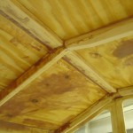
Here you can see the inside of the cabin with the two installed panels. Jointery is fine looking. All the ooze with purple epoxy fillet and knotmarks does not look fine. But all will be covered in white enamel paint, in given time. All of it is sanded, and at least feels very good to the touch. Soft and smooth as… take your pick, for example silk.
-

-
Overall progress as is.
-

-
The two transom knees in place.
-

-
The same small bulkhead epoxied in place.
-
-
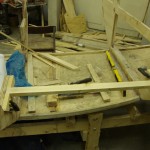
A support for the bench on the aft side
-
-
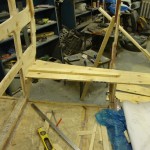
Bench plywood with the support.
-
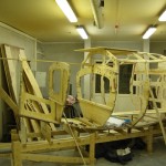
-
The forward bulkhead knee is in place.
-
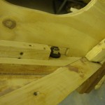
-
The knee and the bolt hole for the forward bulkhead
-
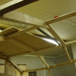
-
The cabin top is supported by these snugly-fitted crossbars.
-
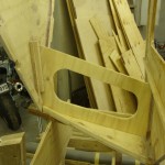
-
The forward bulkhead knee.
-
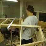
-
Uku working on the cabin top.
-
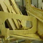
-
Fitting the knee. The sliding bevel was priceless here.
-
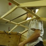
-
The cabin skeleton looking good.
-
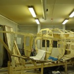
-
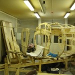
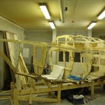
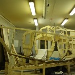
A side view of the boat with the one of the side panels.
-
-
-
-
-
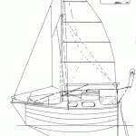
-
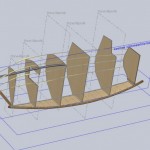
-
-
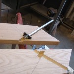
-
A part of the solution for bolting the sharp transom oak to the bulkhead and keelson.
-
-
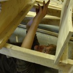
Joosep doing work down below, chiseling washer space for floor bolts.
-
-
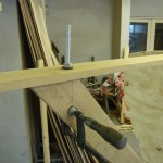
It felt wonderful not having to hold the transom in place with clamps.
-
-
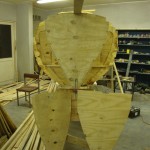
Full house of success and failure. The final bulkhead with two wretches.
-
-
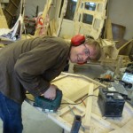
-
Joosep cutting the tiller hole. It proved a wee bit difficult to cut trough the epoxy-plywood laminate. Saw blades heated up very fast and dulled.
-
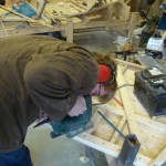
-
-
-
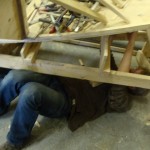
-
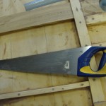
-
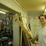
-
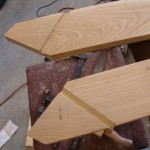
-
-
Fitting the first planks.
-
-
-
A snapshot from inside the cabin. This is the first time we try bending a panel onto the frame – and it worked wonderfully. Cabin trailing stringers can also be seen. These are laminated from plywood. Solid wood proved difficult to bend into the required shape, even after steam treatment.
-
-
-
-
-
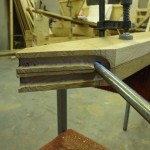
This is the waterline-end of the forward transom. This face joins to the bulkhead. The channel is for a U shaped threaded rod, which goes around the threaded rod which holds the transom and bukhead together. This fixture olds the front down to the keel. There are three bolt-connections from the transom in total. One to the kingplank, one to the keel and one to the bulkhead.
-
-
-
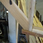
The critical jointery of the transom, before bolting was applied.
-
-
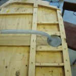
Joosep used our steaming setups end cap as a drawing guide for the tiller hole.
-
-
-
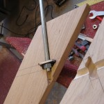
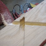
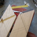
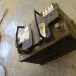
This is how the riveted rods are held in place in the transom laminate. The channels were cut using our plunge router with a round-head bit. Washers were made from milled steel. All the voids will be encapsulated in epoxy.
-
-
-
-
-
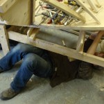
Joosep in a position wihich is bound to lead to spiritual enlightenment if held for sufficient time. Meanwhile beveling bolt holes for the stern transom.
-
-
-
-
-
-
-
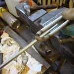
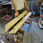
This is how our transom looks like. A two piece laminate. What is not seen on the picture are countersunk clamping bolts, 10 in total, which keep the two sides together.
-
-
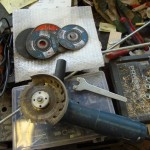
One of the more bad-ass tools we came up with. A circular saw blade fixed to an angle grinder.
-
-
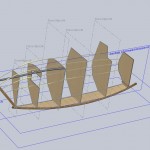
This is the 3d model of the boat as it is physically, that is including our deviations from the plans.
-
-
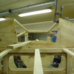
View ahead. The stern “deck” has five stringers in total, three seen here. The cabin entrace is bordered by three stringers, one of which has not been installed yet.
-
-
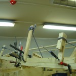
Looks like a Roman war machine. Which it almost is if the forces were to be released in your face, which is about the convenient height for the setup. Used very many clamps, ropes and even a go-cart motor to pull the stringer into place. The whole boat warped and I had to use support structures around the boat to keep it grounded. Later, the wood sprung back too much to be anything other than sinister. Thus the plan was dropped and now these cabin roof-deck transition stringers are made of laminated plywood. More pictures of that very soon.
-
-
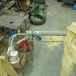
The steaming setup, with the siamese kettles going about their business. I fixed the pipe to the chair with rope. There is a plywood support wedged between the backrest and the pipe, giving a tilt for the condensated water to flow out and also acting as a pipe fixer.
-
-
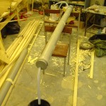
The good side of having a 5 m long steaming tube made of 3 sections is that we can easily shorten it. Here is a 2 m segment that I used for steaming the cabin stringers. Initial warmup time is naturally shorter for a shorter tube, which is a timesaver.
-
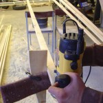
-
Bevelling with the router. Definition of woodworking power – fast, noisy and lots of dust.
-
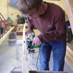
-
Joosep trimming our newly bought stringer wood. We will also round-bevel the edges. Once applied it would be tedious to produce the rounds.
-
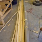
-
Our heap of stringers. All cut to size, some bevelled.
-
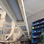
-
The strongback from below.
-
-
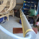
Setup at our shop. The pipe is fixed to its strongback to keep it from deforming under heat. Testing showed that wrapping the pipe with rags is not necessary. Nor is it a must to pre-soak the wood. Perhaps so in hard bend situations, which ours is not. Saves us a ton of problems, otherwise we would have had to build a 5 m long bath for our planks. Using the tube as a soaker would have meant extra time spent.
-
-
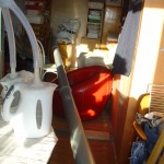
First tests of the steamtube. What better place to perform it than your kitchen. Only this time the end protrudes into the livingroom. The PVC pipes developed a significant bend when not fixed to the strongback. Took about 5 minutes before proper steam started coming out of the end. The pipe is 5 m long after all.
-
-
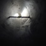
Here you see the inside of the tube, we put nails trough the sides to keep the plank up in the flow of steam.
-
-
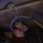
The aorta of the steamer works like a charm. We now have a proper extention cord. This on-the-edge setup here is temporary. 1.7 L of water gets boiled with 30 minutes.
-
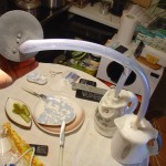
-
The paried kettles connected to one of the end caps of the PVC piping. We decided to join the tube to the cap under an angle, yielding a rotation of steam in the tube. That should give better results, we hope.
-
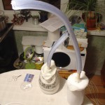
-
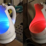
The Siamese water kettles. The good and the bad twin.
-
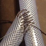
-
Simple wire hook used to pull the stitches in. The Y joint really was tight. I blew trough the hose, barely a hiss from the stitches. I used a 1 mm drill bit to predrill the holes. It is possible to push trough the needle, but why the extra pain?
-
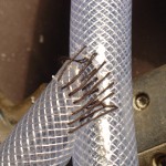
-
Higher levels of stitching. The method is to do all the stitches loose, then tighten them up. I ended up stitching with a 1 cm needle, cut from a perfectly fine sewing needle.
-
-
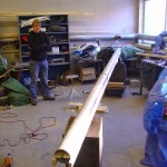
Joosep staning next to our steaming test setup. We will use our garages powerful ventilation to condensate the steam, keeping it away from the inside room. I bet the moisture content in the room would rise after a day of steaming. Like a sauna. Notice the strongback under the piping. The tube will deform under heat. The strongback will keep it firm. We will wrap old rags around the whole thing to keep it warm and condensation as low as possible, to get the hottest steam.
-
-
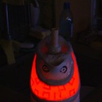
The halloween kettle.
-

-
-
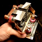
I present, Big Bertha, the 4 kW DC rectifier. The design is nothing fancy, just a lot of cast aluminum cooling and some flattened copper pipe.
-
-
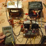
Then we also built a welder out of microwave oven transformers. Here the output is rectified with a 250 A diode bridge.
-
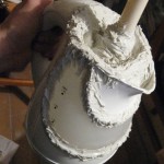
-
I patched it all up with some RTV silicone. This stuff was awful, dried for a month. Okay, okay, the date had expired, but still, that is no excuse.
-
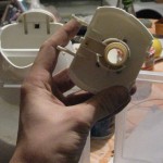
-
Top part of the steam’n tube.
-
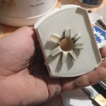
-
Here is the top part, or the steam exhaust being built. Very simple, I did not spend any time on making it look good, as it only has to do what it is supposed to do, which is boil, not win beauty awards. The “rose” you see is there so that bolts could be fitted trough its petals, to keep the tube in place. A plastic washer went on top of the rose, bolts trough that.
-
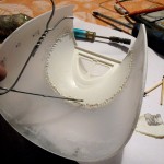
-
Beauty takes its toll. The kettle has a nice see-trough finish, but it cracked at the intersection. I “welded” it back together with a jewelers torch and some coat hanger wire.
-
-
Checking for operation after severing the boiler of its temperature control. Works fine. Did not keep it on for too long, as the plastic will melt without water in it.
-
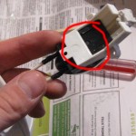
-
Here is the switch which was in the handle. The kettle actually has a passage built into it, trhough which steam will go into the handle to wash agains the metal flipper switch. On the picture, unfortunately, I have already removed the disk.
-
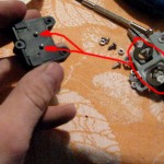
-
A detail of the switch operation. When activated, the metal disks on the right press on the little white knobs on the left. This cuts the power. The black box with the white knobs looks pretty neat inside as well. A surprising design in its complexity, but using thermistors would require the use of some kind of transistors, meaning that his metal-plastic setup is cheaper.
-
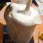
-
Ahh, smells awful, like a pair of rotten socks. Acidic RTV silicone. But this one works like a charm compared to the first kettle. After an hour it was dry to the touch, a bit squichy on the inside. Once cured, the working temperature is -40 to + 150 C. Suites just fine.
-
-
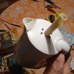
Kettle nr. 2 viewing from top. The steaming tube is visible. You see it being held in place by some nuts and bolts. This is important, since we will be fitting the steaming hose on and off the kettle, it must hold in place when force is applied.
-
-
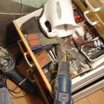
Now, this is why I deserve a… prize. How to dry your water boiler. Why sure, take a heat gun, balance it on your drawer, then aim it at your desired kettle opening. Works like a charm.
-
-
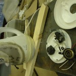
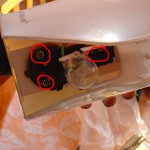
Here are the guts of boiler nr. 2 (sounds like the Titanic sinking). Three metal disk switches in this kettle. Two at the heating element and one in the handle, as with the other boiler. These were easier to remove.
-
-
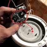
After some time of pondering I finally figured out that the temperature switch is actually something pretty elaborate. The principle depends on little metal disks which snap-bend when temperatures near 100 C are acheived. Pretty neat. These sappers then push little tumblers which in turn cut the power to the kettle. On the picture you see two disks which were pressed agains the boiling element. There is also a switch in the handle, we’ll see about that in a minute.
-
-
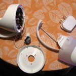
Here you see the guts of one of the boilers being torn out. The purpose of this was to find the temperature switches, which I thought to be thermistors, but I was gravely mistaken..
-
-
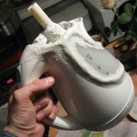
Smoothened it out with some soap water, the evil grin on the kettle looks better.
-
-
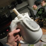
Kettle no. 1
-
-
A little closer detail of the fillet-glass.
-
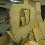
-
The bulkead epoxied, bolted, clamped, filleted and glass taped.
-

-
Fresh stringers with fresh epoxy.
-
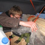
-
String theory in action. Joosep is tying down the trunk with some string.
-
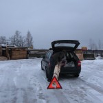
-
Don’t ram this!
-
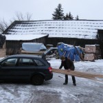
-
Fitting the wood into the car.
-
-
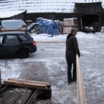
Here is Joosep dragging the timber to the small car. The weather was awful, raining, windy, cold and wet. Talk about winter, last year this time we had a meter of snow and -20 C.
-
-
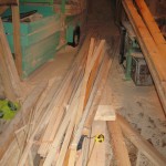
We sorted out a pile of stringers.
-

-
The mill we bought our wood from. The guy operating the saw was always in a good mood, which was nice. Later that day we got some crumpled face treatment at a local tool supermarket. A customer service contrast.
-

-
The stringer wood assortment landed safely at our garage.
-
-
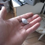
Here is the result. Feels fantastic to pour your first aluminium form. Resembles a horn cleat, does it not?
-
-
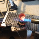
Dont drink this! I used a stainless steel candle holder as the crucible. Inside you see the glowing pool of molten aluminum. They say that dark/medium bright orange is just the right temperature for aluminium pouring.
-
-
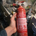
A fire extinguisher, cut it in half and you have a fine crucible for bronze/aluminium purposes. I might get a larger one.
-
-
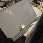
Here you see the ingot cooling on some old music players chassis. As soon as I poured the metal onto the form, the wood underneath literally started burning, hot stuff.
-
-
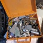
The source of aluminium. I have a small plastic case with small metal bits, which went trough a hot recycling.
-
-
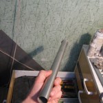
I imagine this stainless teel tube will make a fine butane burner for the future furnace.
-
-
I bought a larger butane torch some time ago with the purpose of soldering silver. Now it was used to melt aluminium.
-
-
-
-
-
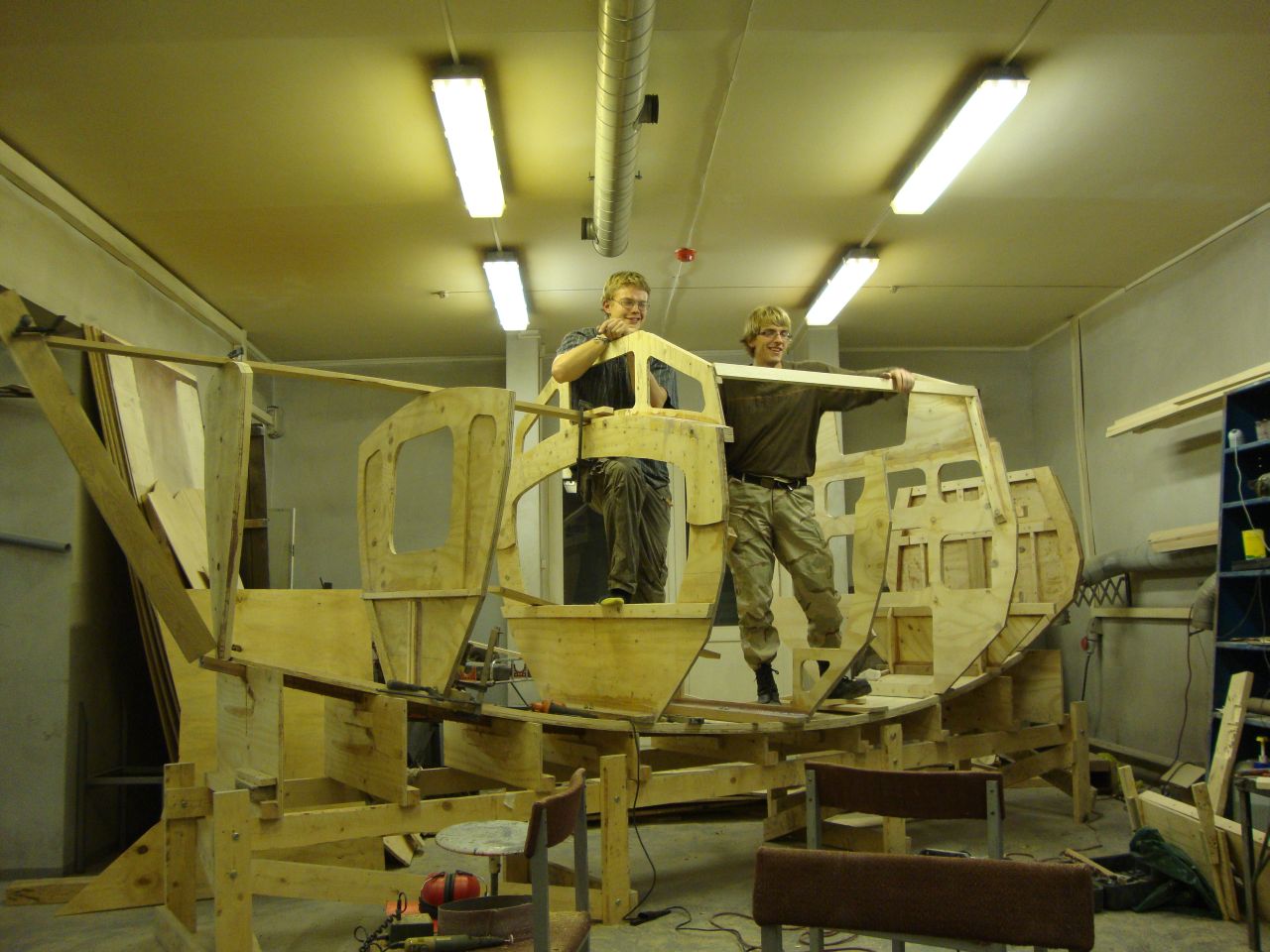
Posing for a picture after sucessfully completing the painstaking transom build. All bulkheads are in place now, sometime 2012., maybe spring?
-
-
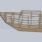
We also tried modelling the whole boat in SolidWorks, a project by Joosep. The idea was to find a good setup for the forward bow.
-
-
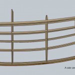
A side view of the Fafnir boat, modelled on a computer for easy adjustment.
-
-
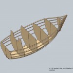
Again, note the strange droplet-like shape that the top stringers are trying to make. This is due to the additional bow stem, giving extra length. The forward bulkhead should be made correspondingly wider.
-
-
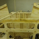
An inside view on the aft bulkhead
-

-
A view on the stem
-
-
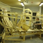
A side view of the boat with two of the top stringers in place.
-
-
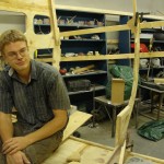
Not only did we crack stringers. Here is Uku after having sat on the central bulkhead when stringer load was tested. The bulkhead cracked.
-
-
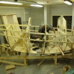
-
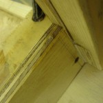
The crack from the floor’s side.
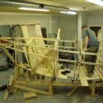
-
-
The ships skeleton
-
-
Stringers on the boat
-
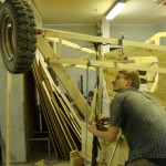
-
A view on the stem with the stringers attached
-
-
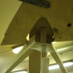
A tool for holding stringers to the transom. We called it the “heart clamp,” or the “kiss clamp.”
-
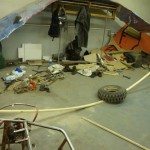
-
Wonder why did we crack so many stringers?
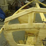
-
-
A view on the stringer as it attaches on the bulkhead.
-
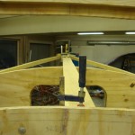
-
A view on the kingplank wiht the stringers attached.
-
-
-
-
Bringing (bending) the best out of the wood.
-

-
Pointing at the direction of travel.
-
-

-
-
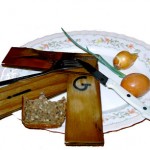
Mmm.. delicious high fiber food.
-
-
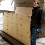
Joosep on the day our wood arrived.
-
-
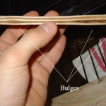
The most significant change occurred in the overlaps of the veneers. On the picture you can see that the overlaps have bulged out significantly. This might be a source for delamination in the long term. An epoxy strong back ought to help.
-
-
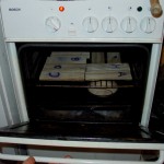
Brave little test pieces subjected to 300 C for 20 minutes.
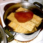
-
-
This is how we boiled them. The stone was added ontop to keep the plywood soaked, as the mixture boiled with vigor.
-
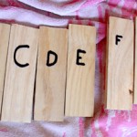
-
None delaminated.
-
-
-
WiTHiN human powered expedition boat
-

-
-
-
-
-
-
-
-
-
-
-

-
-
-
-
-
-
-
-
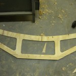
Meanwhile we had cut out the first cabin windows.
-
-
-
-
-
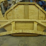
Here you can see the windows segment which was cut out of our lap jointed plywood plate.
-
-
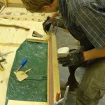
Here you can see the process of epoxying the floor to the bulkhead, as well as filleting it and glassing it.
-
-
-
-
-
-
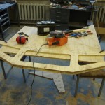
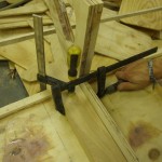
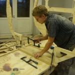
Fitting the midship floor to its bulkhead. The floor here has already been beveled.
-
-
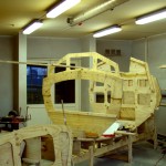
Front windows applied.
-
-
Notice the fine use of weights in our garage. A wrench case, lead acid battery, go cart motor and our HIWA (Heavy Important Welding Apparatus). The plates were fixed on the floor with car wheels.
-
-
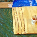
Getting ready to epoxy the first joint. I belt sanded both the laps. The cross section of the lap looks nicer now. Plenty of epoxy was used here, since the endgrain of the wood absorbs most glue when compared to the rest of a plywood sheet. And here, you see a very wide endgrain exposure. The long bar in the upper part of the picture is for keeping a straight edge reference. It is actually our future bow stem. The work is laid onto a plastic sheet so that we do not glue the lap joint stuck to the floor. It has happened that I have glued a bulkead to the floor. The bulkhead did not yield, but the floor did, which I find interesting.
-
-
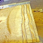
First completed half of a lap joint. Notice that the cross section of the plies is not uniform. This is because the router bit varied in height due to the unnevenness of the guide bevels and the router plate itself, which I had to extend leghtwise in order to get it to work. Also, I added some material to the guide bevels when you compare to the first picture, to give the router bit space to work. I ought to have planned the lap joint rig forehand. For exmaple modelled it out in SolidWorks. If you plan on building a set up, sketch it down first.
-
-
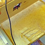
Our lap jointing setup.
-
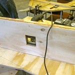
-
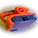
The bottom of the router plate. All is looking good. I sanded the plate with our belt sander to give it a smooth finish.
-
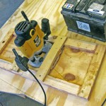
-
Another shot of the jointer.
-
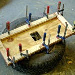
-
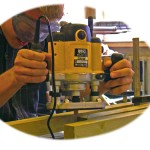
Here you see the plate for the plunge router. There is a hatch to allow for the router bit to go trough and also, what is important, to see what the router bit does. That is why the hole is oversized.
-
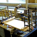
-
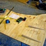
Epoxying the bevels onto the base plate of our router base. The plywood we use is not all that straight. Keep that in mind when creating a lap joint setup, you want it all to be level.
-
-
Here you see the joint setup. We used a 12/1 lenght to thickness ratio as recommended by “The Gougeon Brothers on boat construction” book. It is a good book, check it out.
-
-
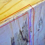
A finished lap joint. The red outlines the joint. Barely visible. The black you see is some motor oil I managed to spill, fortunately most of it spilled on me, no the plywood. I gave the joint some good heavy thumps with my fist and it ringed like a solid piece of wood. Out of this piece we will make our fore cabin windows.
-
-
-
-
-
-
-
-
-
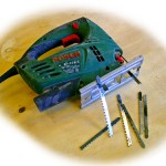
Our jig saw
-
-
-
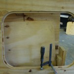
This is where the watertight bulkhead hatch will go
-
-
Beginners woodwork on the reinforcements for B#1
-
-
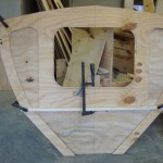
This is the first bulkhead – B#1. There is an opening for a watertight hatch that’ll open to a supply cabinet in the bow.
-
-
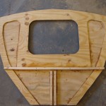
Here we’ve glued the reinforcements to the bulkhead.
-
-
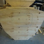
This is the front bulkhead with the hatch closed. This is how it’ll look like from the inside, looking to the bow.
-
-
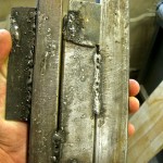
Here you see some very important metal pieces welded together. To the right are some more or less decent welds. The rest you see is sputter. It all holds together though, I gave this unification of metal a good hammering and all I got were dents. I will put this on Ebay and get rich, ye?
-
-
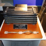
In the summers, Joosep has been working at CERN. This one was used for superconducting magnets in CERN’s Large Hadron COllider until it burned out due to a manufacturing fault.
-
-
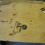
Drawing out the doubler for the B#1 bulkhead on 9mm plywood
-
-
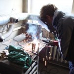
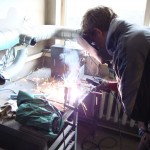
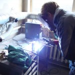
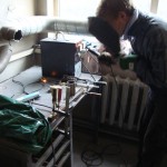
Uku welding two very important pieces of iron together to an even more important piece.
-
-
-
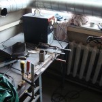
Welding was great fun and kept us from building the boat for some time.
-
-
-
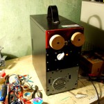
-
Here you see the buzzer box from outside.
-
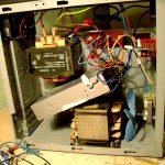
-
Here you see the very not so complicated wiring of the welder.
-
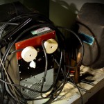
-
What a beasty!
-
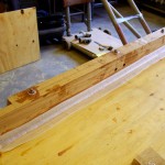
-
I cut the glass tape to lenght and fixed it straight to the fillet. It sticks well and you can easily do fine adjustments before applying epoxy.
-
-
I added the fillet straight after fixing the timber in place with scres and bolts. Makes things faster and promises less sanding. I used a round scoop I cut out of one of the lids of the jam cups used for mixing epoxy. Gives a nice round fillet.
-
-
The epoxy has been laid, screws screwed and bolts bolted.
-
-
When starting to epoxy the floor timber to the frame I have set up all the things I might need. Clamps, a wrench for bolts, glass tape (in the bag), a knfe, a custom cut filleting roundedge, sandpaper and a block of wood, a drill with a screw bit attached. The epoxy is in the jam jar.
-
-
Here you see a nice furniture bolt fitted trough the timber and bulkhead. Always mark where you put your bolts or screws – it keeps your work tidy.
-
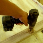
-
Drilling the 10mm holes for the floor timber. The bolt goes trough the timber, bottom panel and keel.
-
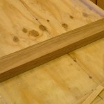
-
What a nice fit to the logs! The router is a good tool.
-
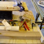
-
Settting up for the other side of the timber.
-
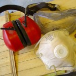
-
Very good accessories to have when routing. My router makes a ton of noise when ripping trough the wood. I’d still like to listen to birdsong in the future. The dust mask is good unless you hold your breath, lots of dust is produced. Eye protection! Yes, that is a must. I’ve had burning bits of iron in my eye, ever since I am cautious.
-
-
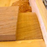
A very nice slot for the chine log to sit in. Now for the other side!
-
-
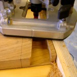
Coming along well. I had to do the cut in two depth sets.
-
-
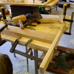
To cut the joints for the chine logs I used a router. It gives you a very fine edge with low error. I chiselled the first three floors, but routing is better. Here you can see the setup. The floor is fixed to my “work desk” with a clamp. The guide rail is a simple wood scrap piece fixed to the desk with some clamps in an improvised fashion. Without the guide rail the router would perform havoc on the timber.
-
-
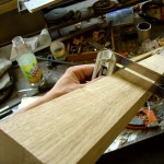
The adjustable bevel can now be used to check for irregularities in the planing process. Looks fine!
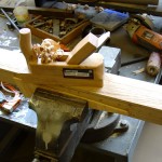
-
-
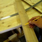
I hand planed the timber. To make sure that you have a nice flat surface, perform some strokes diagonal to the wood grain. That ensures a nice plane surface.
-
-
Some tips for planing
-
-
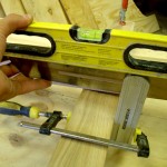
It is important to get your floor timber level to the horizon.
-
-
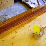
The tape has been soaked with epoxy. I coated the timber with the excess.
-
-
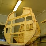
Three bulkheads stand tall. Taped, sanded, screwed, bolted – they got it all.
-
-
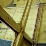
You can see the bolts here, trough the floor and the keel.
-
-
Reading up on wood types
-
-

-
The cheap ones are good and sloppy. The expensive ones are not that fun.
-
-
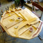
On the right side you can see the butt joints under a layer of epoxy. My gut feeling tells me that a simple butt joint wont do. The extra layer of ply is laying on its back on the middle of the picture. The left side of the transom has already been fixed with clamps.
-
-
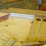
Glass tape laid onto the wet fillet. It sticks well and you can tap out uneven regions.
-
-
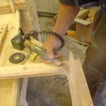
The hard way of glassing fillets. Let the fillet dry and then dremel it to a round edge. I only used the dremel on the corners, the rest was done with sandpaper.
-
-
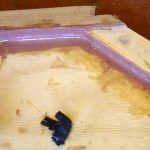
The glass is soaked and eager to dry. Notice that it sits rather well, no bulges or dents. This is because the glass was laid onto a wet fillet.
-
-
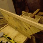
The small bulkhead dry fitted with bolts trough the keel.
-
-
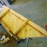
A small bulkhead right next to the stern, the epoxy is drying as I type.
-
-
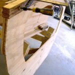
In the last post you can read about laminating the arch seen on the picture. It will sit comfortably under the mast step.
-
-
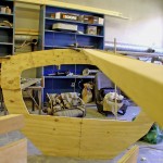
Midship bulkhead onto which the mast step will be fixed. The placement of the king plank can be seen as well. The cabin windows also grow out of this frame.
-
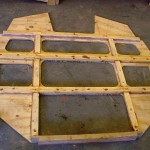
-
The bulkhead with the cabin entrance, support structures in place on the stern side.
-
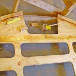
-
On this image you can see the epoxied glass tape over the joint of three plywood plates. Also, the support structures facing the bow are in place to strenghten the edges of the cabin.
-
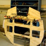
-
The cabin entrance bulkhead is made up of three separate plates. They are held in place by the crossbar seen on the picture. A fiberglass tape seam is on the other side.
-
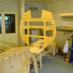
-
The bulkhead with the cabin entrance is showing signs of independence. I do not have to hold its hand every time it is vertical.
-
-
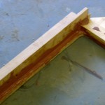
Floor timer fixed to one of the bulkheads, the purple epoxy filling is visible. To be sanded and taped.
-
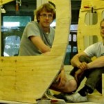
-
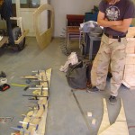
-
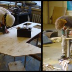
The arch support for a bulkhead lies awaiting good’ol epoxy, being bent by clamps. Notice also how Joosep still has a bent neck.
-
-
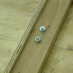
-
Vastu vaatavad kaks polti, mis seovad kokku kaare floori ja kiilsoni. Antud juhul on tegemist 1cm läbimõõduga poltidega.
-
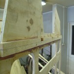
-
Pildil on näha kajuti luugiga kaart, mis on valmistatud kolmest osast. Seisab juba omal jalal, st. floori küljes!
-
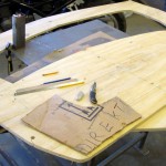
-
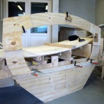
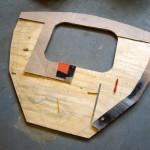
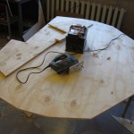
Making of the central bulkhead.
-
-
-
-

-
-

-

-
-
-
-
-
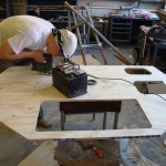
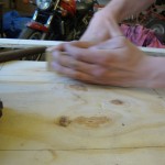
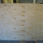
Cutting out the first frames.
-
-
-
-
-
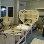
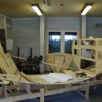
Laying out the first bulkheads.
-
-
-
-
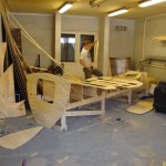
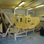
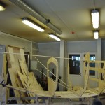
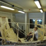
What a wonderful moment to see the boat take shape. Summer of 2011.
-
-
-
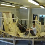
-
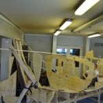
-
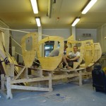
-
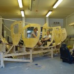
-
Posing for a picture.
-

-
Joosep cruising along. This was in 2011. spring when we had just started the build.
-
-
-
-
-
The B#2 arch on plywood
-
-
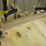
The sternmost floor
-
-
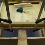
A different view of the stern floor
-
-
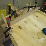
The stern floor, clamped, bevelled and dry-fitted
-
-
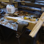
Fitting the stern floor
-
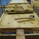
-
Bottom stringers in place
-
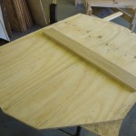
-
Stern transom
-
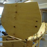
-
Stern transom in place
-
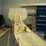
-
Aft transom resting on some scrap wood.
-
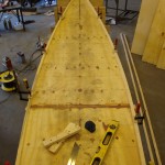
-
Chinelogs on the laminated, 18 cm shorter than planned floor.
-
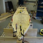
-
Chine stringers bent in place.
-
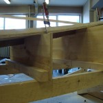
-
Bottom plate glued in place
-
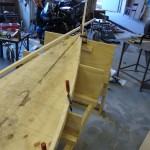
-
Bending the bottom stringer
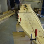
-
-
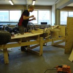
Bottom stringer, bent to place
-
-
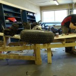
Last touches with epoxy
-
-
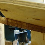
Põhjaplaadi raskused
-
-
The stern, bottom plate nicely glued in
-
-
The bottom plate fitted to the keelson
-
-
DIY clamps
-
-
The central bottom plate joint, epoxied
-
-
Applying pressure to the bottom plate
-
-
Improvised clamps
-
-
The bottom plate on the keelson
-
-
Fitting the bottom plate
-
-
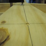
A screw through the bottom plate to the keelson
-
-
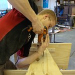
A counter-sunk hole
-
-
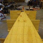
Dry-fitting the bottom plate
-
-
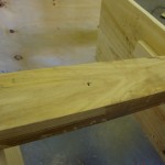
The centered bottom plate.
-
-
A screw hole in the keelson
-
-
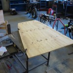
Cutting the bottom plate
-
-
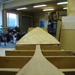
The bow part of the bottom panel
-
-
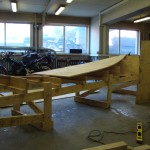
The bottom panel on the jig
-
-
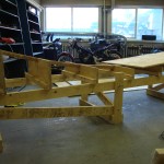
The stern part of the keelson
-
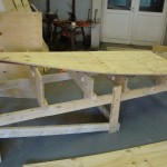
-
The bottom panel on the jig
-
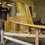
-
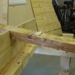
Põhjapaneel
-
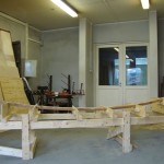
-
The keelson after the epoxy has dried
-
-
The laminated keelson.
-
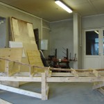
-
Keelson without the clamps
-
-
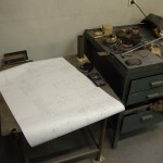
Drawings
-
-
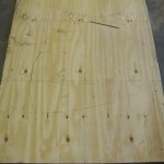
Drawings on plywood
-
-
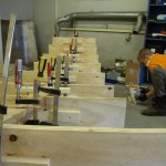
Keelson in the jig.
-
-
-
Keelson, laminated, stern
-
-
A MacGyver-clamp
-
-
Sanding the keelson before laminating it. A friend, Eero, is helping.
-
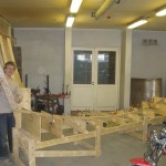
-
Bow transom
-
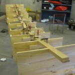
-
Jig and keelson
-
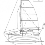
-

-


I am looking forward viewing to the latest build photos.
Are you planning to fabricate your own sails?
Cheers
Hello!
Well, we are getting back into the build now after a summers’ “vacation”, so pictures will have to wait for a few weeks. We have not had a serious look at sails yet, only somewhat. Fabricating our own is an option, but we will concider having them made or buying them secondhand.
Cheers,
Uku
Hello!
I live in Sweden and like you guys i have found insperation from Sebastian Näslund and Sven Yrvind to build and sail a small blue water sailboat far across the oceans. I found the “fafnir” while searching for micro blue water cruisers.
I been wanting to sail around the world in a small sailboat since i was 10.
Now to the two questions i have:
1: How much do the fafnir cost to build in euro? (not including the rigg and sails)
2: You mentioned the space needed to build fafnir. I only have a 1 car garage and i wounder is it possible to start the construction of the fafnir inside a 1 car garage and then continue outside when its time to mount the keel? I Think the hight of the garage door is about 1,70 cm
Cheers
Ps: i´m happy to have found your website and it contains many helpful tips!
Hello, Mattias!
Glad that you like the boat and share a dream. Fafnir has cost around 4 k EUR so far, not including rigging, sails, paint and some other little things. Epoxy has been the most expensive article, we have bought 3 patches of 30 kg (25 kg resin, 5 kg hardener) and that is about 2 k EUR. Largely because we decided not to build the boat out of marine plywood. If money is an issue, go with marine plywood. It seems expensive at first, but will pay off later. As long as your garage is long enough (slightly over four meters), then starting the build in the garage is no problem. Though more space is better. You can, for exmaple, cut out all the bulkheads, add all fixtures to them etc. I’d advise building a small model before jumping to the big one. Buy some balsa wood from a hobby store and figure the things out to scale. This helps you figure out the plans, which is not as simple as one would think. If you have any more questions, feel free to ask. I have to eat breakfast now 🙂
Cheers,
Uku
Thank you for the answers!
I will messure the garage space but i know that it is at least 5 meters in lenght and i messured the garage door today and it was 195 cm, not 170 cm as i assumed.
How long did it take the two of you to build the fafnir?
Cheers
Mattias
Hello!
Well, it has now taken us three years. During the time we had a very scarce building schedule, being students and employees and all that stuff..
Now it will also depend on the width of the garage, if you wish to complete the whole hull inside.
Cheers,
Uku
Hello again!
Thanks again for the answer.
I belive that it would take me even longer due to the fact that i´m building alone and have a full time job plus a baby.
But im not in a hurry =)
As long as it seems manageable to build it alone with somewhat limited boatbuilding knowledge.
Will it be able to steer from both the inside and outside?
Does it have a small cockpit or is the aft deck enclosed? (it´s hard to tell from the pictures and drawings i have seen)
Hello!
Yes, you can steer both from the inside and on deck. The aft deck is closed, a small, perhaps 1 sqm or so of space to sit on, with a most probable sailing setting of legs in the hatch. The boat is actually quite roomy inside, you’ll fit 4 “large” persons sitting face to face inside, two on either side. There are compartments all over, in the seats, side shelves, a watertight compartment and a large compartment right under the mast. No standing room though, unless you are 1,6 m tall or so.
Cheers,
Uku
Great website, if possible could you add some photo’s of the inside of Fafnir and the tiller and inside steering system.
Seriously thinking of giving this a go and would be very interested in those details.
Hello, John!
Thank you for the kind words. We have not implemented the inside steering system yet, but we did build a mockup of it. To our experience, steering from the inside would give good shelter from cold winds and water spray. We will install the second tiller next season. I will take pictures of the inside the next time I go sailing.
Cheers,
Uku
Thanks Uku!